
|
|

|
|
|
|
Welcome to the Australian Ford Forums forum. You are currently viewing our boards as a guest which gives you limited access to view most discussions and inserts advertising. By joining our free community you will have access to post topics, communicate privately with other members, respond to polls, upload content and access many other special features without post based advertising banners. Registration is simple and absolutely free so please, join our community today! If you have any problems with the registration process or your account login, please contact us. Please Note: All new registrations go through a manual approval queue to keep spammers out. This is checked twice each day so there will be a delay before your registration is activated. |
|
|||||||
 |
|
|
Thread Tools | Display Modes |
 18-09-2010, 07:28 PM
|
#1 | ||
|
Noctunral by nature.

Join Date: Mar 2007
Location: NSW,mid north coast.
Posts: 296
|
After the First connector coming directly from the o2 sensors on the au v8 does wiring go thru any other connectors/junctions?
im having wildly fluctuating voltage from mine from .2 to 2.5volt. Or is it simply, Sensor>Connector>ecu.
__________________
98 Au V8 Forte (1500 kilo car) LSD, Pacie comp extractors into pacie cats into lukey 3" exhaust, New ecu, Powerbond street balancer, injectors, tyres (on 17" tickford rims form factory) Slotted and cross drilled rotors front and back, New radiator and hoses new crank position sensor and cam sensor plus gear, new leads and iridium plugs and new accel coil packs. New S5 solenoid. plus flash tuner (SCT X3 flash tuner) |
||

|

|
|
18-09-2010, 11:23 PM
|
#2 | ||
|
Regular Member

Join Date: Oct 2006
Location: Naracoorte SA
Posts: 168
|
All wires for HEGO's go directly to pcm without any junctions apart from the B+ve for the heater circuit (goes through fuse box, etc) Only have wiring for series II , but I would assume series I would be the same.
Wes
__________________
White MY04 Subaru Impreza WRX Hatch - Stock, airbox resonator mod, lowered on king springs Marine Blue EBII XR8 - GT40p's, Paceys, 3in mandrel bent exhaust, Explorer Manifold, YT 1.72 RR's, 65mm TB, 75mm MAF, Thermo's...now manual  1967 Ford Futura coupe 289 C4 stock cruiser
|
||
|
|
|
|
22-09-2010, 03:54 PM
|
#3 | ||
|
Noctunral by nature.
Join Date: Mar 2007
Location: NSW,mid north coast.
Posts: 296
|
Now the best question, are there any common places the o2 sensors wiring likes to break, fowl, ground, short etc.
According to the Haynes book there are to joins for bank 1 o2, they are markerd c-119 im not sure what they sand for, just says c-119 inside i sqaure and thats all, theres 2 of them in line. connected to wires hego 2 dosent have these.... they are connect to the two wire gy-w and gr-L gy=grey gr=dark green w=white L = Dark blue
__________________
98 Au V8 Forte (1500 kilo car) LSD, Pacie comp extractors into pacie cats into lukey 3" exhaust, New ecu, Powerbond street balancer, injectors, tyres (on 17" tickford rims form factory) Slotted and cross drilled rotors front and back, New radiator and hoses new crank position sensor and cam sensor plus gear, new leads and iridium plugs and new accel coil packs. New S5 solenoid. plus flash tuner (SCT X3 flash tuner) |
||
|
|
|
|
22-09-2010, 09:33 PM
|
#4 | ||
|
Regular Member
Join Date: Oct 2006
Location: Naracoorte SA
Posts: 168
|
sorry man, you're right bank 1 HEGO does have 2 connectors (oversight on my behalf
 ) between it and pcm, c119 and c33. The GY-Y wire is 12v from PCM power relay, BK-W should be earth from PCM, GY-W should be earth to activate heater circuit from PCM, and DG-DB is signal return to pcm from sensor. C119 is a white 44 pin connector located on LHS of vehicle (looks to be rear of engine bay or maybe above pcm area?) and C33 is a 44 pin orange connector, diagram shows it on the RHS possibly behind kick panel it's hard to tell from the connector location diagrams. ) between it and pcm, c119 and c33. The GY-Y wire is 12v from PCM power relay, BK-W should be earth from PCM, GY-W should be earth to activate heater circuit from PCM, and DG-DB is signal return to pcm from sensor. C119 is a white 44 pin connector located on LHS of vehicle (looks to be rear of engine bay or maybe above pcm area?) and C33 is a 44 pin orange connector, diagram shows it on the RHS possibly behind kick panel it's hard to tell from the connector location diagrams. Wes
__________________
White MY04 Subaru Impreza WRX Hatch - Stock, airbox resonator mod, lowered on king springs Marine Blue EBII XR8 - GT40p's, Paceys, 3in mandrel bent exhaust, Explorer Manifold, YT 1.72 RR's, 65mm TB, 75mm MAF, Thermo's...now manual 1967 Ford Futura coupe 289 C4 stock cruiser
|
||
|
|
|
|
22-09-2010, 09:38 PM
|
#5 | ||
|
Chairman & Administrator
  
Join Date: Dec 2004
Location: 1975
Posts: 106,943

|
HEGO1 sensor travels through a number of connectors before getting to the PCM.
The GY-W wire along with the DG-DB go to C-33, then to C-119 before joining the ECU at Pins 4 and 35 respectively. The GY-Y wire travels through C-33 and C-158 before splitting so that one wire goes to a 15A fuse at C-163 and the other goes through C-125 to join with HEGO2 sensor at C-130 and then on to Pin 23 (as an Orange wire) at the ECU. The BK-W wire from the other side of HEGO1 also goes through C-33 and C-119 before joining a common earth point. I've enclosed diagrams of C-119 and C-133  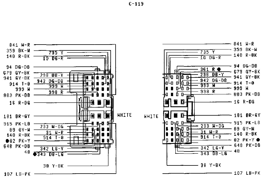 Cheers Russ
__________________
 Observatio Facta Rotae
|
||
|
|
|
|
22-09-2010, 09:41 PM
|
#6 | ||
|
Regular Member
Join Date: Oct 2006
Location: Naracoorte SA
Posts: 168
|
repost
__________________
White MY04 Subaru Impreza WRX Hatch - Stock, airbox resonator mod, lowered on king springs Marine Blue EBII XR8 - GT40p's, Paceys, 3in mandrel bent exhaust, Explorer Manifold, YT 1.72 RR's, 65mm TB, 75mm MAF, Thermo's...now manual 1967 Ford Futura coupe 289 C4 stock cruiser
|
||
|
|
|
|
24-09-2010, 11:21 PM
|
#7 | ||
|
Noctunral by nature.
Join Date: Mar 2007
Location: NSW,mid north coast.
Posts: 296
|
Yes there are 2 white c-119 connectors under the dash one next to the orange one above accelerator pedal and the other to the right of the ecu passenger side dash, no other connectors that i can determin in the engine bay, the ones on driver side can be lower by undoing 2 13mm bolts from memory. allowing for good penetration of contact cleaner.
I did the key on Engine not running datalog to see what the hegos did, which was which side tests etc my findings where. (connected hego 1 at a time per side and logged till hego was fully heated. they start off as very low then they jump to both .4volts then drop taking 360 seconds both to stabilize at 0.087v engine not running just sitting in engine bay. checked to see if they heat up and yes both when the hego was connected on either side was smoking hot. Bank 2 aswell if anyone want to know is passenger side. heres a datalog from today, half the time the 02's voltage just drop to .2, then they can peak up and down on and off... and heres a mix of all of the above... strange how the timing is muckin around aswell??? 
__________________
98 Au V8 Forte (1500 kilo car) LSD, Pacie comp extractors into pacie cats into lukey 3" exhaust, New ecu, Powerbond street balancer, injectors, tyres (on 17" tickford rims form factory) Slotted and cross drilled rotors front and back, New radiator and hoses new crank position sensor and cam sensor plus gear, new leads and iridium plugs and new accel coil packs. New S5 solenoid. plus flash tuner (SCT X3 flash tuner) Last edited by Mr_Monty; 24-09-2010 at 11:28 PM. |
||
|
|
|
|
25-09-2010, 11:05 PM
|
#8 | ||
|
Regular Member
Join Date: Oct 2006
Location: Naracoorte SA
Posts: 168
|
Not sure about the voltage range but output pattern for bank 1 seems ok, bank 2 however doesn't. Looking at the recording it seems to stay lean for a long time then spikes rich (patterns should pretty much mirror, esp. at idle) and that timing doesn't seem right either. Prob need to scope the O2 sensors at the connectors to get the proper voltage reading, I'll have a look at my ute on the scan tool tomorrow, if I remember, and check what the timing is doing. If your vehicle is smartlock and not smartshield you should be able to borrow a like pcm and leave the key in the 'on' position for 30 mins to code the key barrel to the pcm.
Wes
__________________
White MY04 Subaru Impreza WRX Hatch - Stock, airbox resonator mod, lowered on king springs Marine Blue EBII XR8 - GT40p's, Paceys, 3in mandrel bent exhaust, Explorer Manifold, YT 1.72 RR's, 65mm TB, 75mm MAF, Thermo's...now manual 1967 Ford Futura coupe 289 C4 stock cruiser
|
||
|
|
|
|
26-09-2010, 03:20 PM
|
#9 | ||
|
Cat be Still !!!

Join Date: Oct 2007
Location: Perth. WA
Posts: 1,672
|
Hey Monty good to see the live link working, I can get mine to start and run for a minute or two at or just above idle but not long after im on the road it stops, same problem running through PC or stand alone hand held.
|
||
|
|
|
|
26-09-2010, 03:25 PM
|
#10 | ||
|
Noctunral by nature.
Join Date: Mar 2007
Location: NSW,mid north coast.
Posts: 296
|
You'll notice mine cuts out at the end lol thats cause it cuts out aswell, but a lil data is better then none.
__________________
98 Au V8 Forte (1500 kilo car) LSD, Pacie comp extractors into pacie cats into lukey 3" exhaust, New ecu, Powerbond street balancer, injectors, tyres (on 17" tickford rims form factory) Slotted and cross drilled rotors front and back, New radiator and hoses new crank position sensor and cam sensor plus gear, new leads and iridium plugs and new accel coil packs. New S5 solenoid. plus flash tuner (SCT X3 flash tuner) |
||
|
|
|
|
27-09-2010, 10:06 PM
|
#11 | ||
|
Noctunral by nature.
Join Date: Mar 2007
Location: NSW,mid north coast.
Posts: 296
|
iv tried running it with bank 1 o2 connected only. according to logger its not in open loop... with one 02 or no 02's....
anyway car beheives with just the one connected so.. better then none right? given the side that plays up is the same side i had the bad spark plug insulator leak im going to take a guess and say that spark jumped thru the 02 into the ground into the ecu, given its a completely unprotected circut from my point of view. Still no engine warning lights or dtcs with 1 o2 or no o2's connected.
__________________
98 Au V8 Forte (1500 kilo car) LSD, Pacie comp extractors into pacie cats into lukey 3" exhaust, New ecu, Powerbond street balancer, injectors, tyres (on 17" tickford rims form factory) Slotted and cross drilled rotors front and back, New radiator and hoses new crank position sensor and cam sensor plus gear, new leads and iridium plugs and new accel coil packs. New S5 solenoid. plus flash tuner (SCT X3 flash tuner) |
||
|
|
|
|
02-10-2010, 08:42 PM
|
#12 | |||
|
BUILT FORD TUFF

Join Date: Jan 2005
Location: Mackay QLD
Posts: 1,919
|
Quote:
Hi Gents, I am in the final stages of finishing the T3 Engine into my ED XR8. What i need is a better copy of some of the wiring diagrams. I have had a look at the Tech section and while it is there i cant print it and it is very hard to read sections. The following is what i need scanned so i can print it and blow it up. 1/ Full EFi wiring diagram. 2/ ECU plug pins and colours 3/ ECU pin out numbers and description or Acronym list 4/ The C119 (ford code) plug next to the ECU plug 5/ The C 125 plug near the left headlight 6/ Grounds and power circuits I have an aftermarket wiring diagram and guess what, it does not match 100% so i cant trust it. This is going to help me get this thing going finally. Any help would be much appreciated, Thanks Shane I have copied the C119 that you posted but need the rest. T tried to copy the ones in the tech section but they wont allow it. It would really be a help and save me some time
__________________
2015 FGX XR6 Turbo |
|||
|
|
|


 Linear Mode
