
|
|

|
|
|
|
Welcome to the Australian Ford Forums forum. You are currently viewing our boards as a guest which gives you limited access to view most discussions and inserts advertising. By joining our free community you will have access to post topics, communicate privately with other members, respond to polls, upload content and access many other special features without post based advertising banners. Registration is simple and absolutely free so please, join our community today! If you have any problems with the registration process or your account login, please contact us. Please Note: All new registrations go through a manual approval queue to keep spammers out. This is checked twice each day so there will be a delay before your registration is activated. |
|
|||||||
|
|
Thread Tools | Display Modes |
 28-04-2008, 01:12 AM
|
#1 | ||
|
FF.Com.Au Hardcore

Join Date: Jan 2007
Location: Melbourne northern suburbs
Posts: 4,025

|
Had a few hours spare today so decided to have a go at making a spacer for the airbox in the XR5. For those of you who dont know the ECU actually sits in the airbox and all but covers the inlet horn. Why they put it where they did is anybodys guess but it really does mess with the airflow and reports from some manufacturers of these spacers is that this modification is good for around 12 -14 hp in the upper rev range.
So, with a few hours to kill here is what happened; First up removed all the bits, 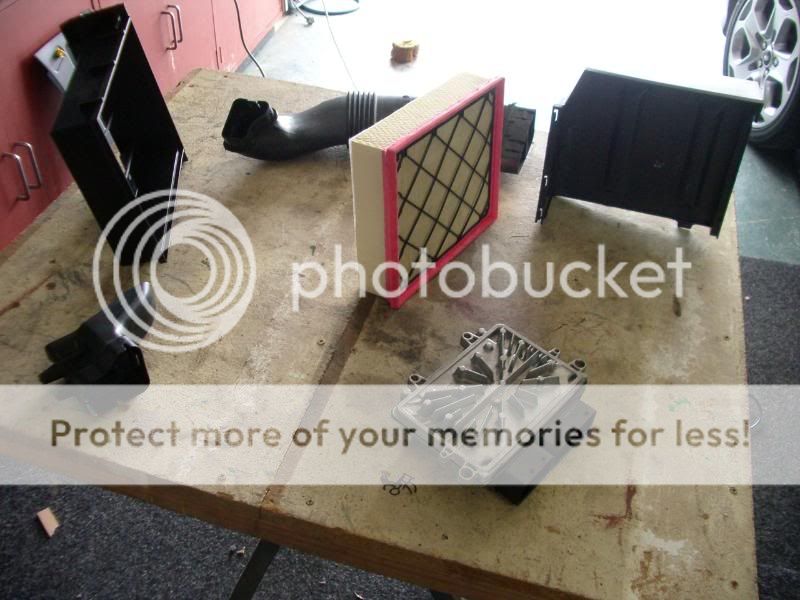 Its a bit hard to describe but the cooling fins on the back of the ECU actually penetrate into the airbox about 10ml, which puts them almost right on top of the air horn!! Not good for smooth air flow.  This is inside the CAI tube, again not a good design for efficient air flow. 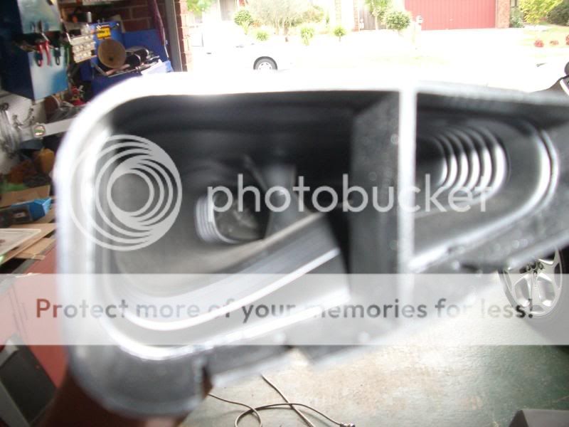 First step was to make a template, first one made of cardboard to get the basic shape, than a more accurate one made from 4ml MDF  Final fitting and some trimming had it close enough to use as a final template 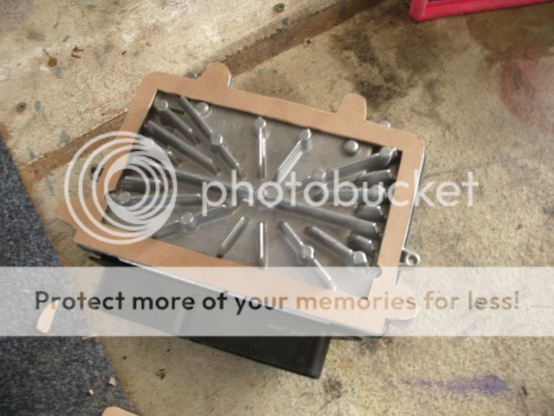 The spacer material I used was just an old nylon chopping board, cheap and easy to work with and more than suitable as a trial spacer. I glued 2 pieces together to finish up with a 14ml spacer. Installed and ready to go 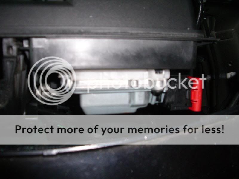 So whats it like with the spacer fitted? Well its no different to drive around normally and 90% of the time you would not know it was there, but! There is a definite improvement in the upper rev range, not sure how much more power it makes (Ill run it up on the dyno in the next few days) but it is much more willing to rev infact its now has a noticeable kick from about 4800 and will spin through to 6500 quite willingly now, where as before it felt labored if you pushed it much past 5000. Having seen the original setup first hand Im not surprised its made a difference, the factory setup really was very restrictive. Ill get my son to draw it in autocad and Ill have a few made out of 12ml alloy plate so if anybody is interested let me know. PS, some people suggest that its put there (in the inlet airflow) to keep it cool, well I gave mine a pretty good work out with everything that I could think of switched on and after some adrenalin charged driving I pulled up and popped the bonnet and the ecu was hardly warm so I dont subscribe to that theory. Only down side is the ECU cover wont go back on (just) so Im hoping that using a 12ml spacer rather than 14ml may actually give me enough room to get it back on. Cheers. |
||

|

|


 Threaded Mode